Showing posts with label part design. Show all posts

Friday, 4 October 2024

Polymer Selection Funnel Example - Smartphone Front Bezel (Consumer Electronics Material Selection)

Hello and welcome to another polymer material selection example for which we use the POMS-Funnel Method (in detail explained here and in this video). Today’s mission is to select the optimal polymer for Liquid Crystal Display (LCD) bezel used in smartphones. 

Figure 1 presents the four different stages of the material selection funnel as well as the tools we can use to facilitate the selection. We can use this as a guideline throughout the selection journey. 

Figure 1: Polymer Selection Funnel - overview of the four different funnel stages and tools.

POMS-Funnel Method: 

Funnel stage 1: Material selection factors

In the first Funnel stage we focus on gathering and understanding all the requirements of the LCD bezel for smartphones (Figure 2).  
Figure 2: Overview of a LCD front bezel used in the iPhone 14 Plus. Aim of the first funnel step is to lay out the requirements.


Covering effectively the product requirements, a combination of functionality questions and selection factor questions can support you to achieve this. First we have to ask some questions on the functionality of the part. 

Following questions can help us with this assessment:
-What are the performance requirements (structural, etc.)?
-Do you want to combine multiple parts or functions?
-What will be the structural load of the part (static, dynamic, cycling, impact, etc.)?
-What will be the environmental impact on the part (chemical, temperature, time)?
-What is the expected lifetime of the product?

After answering the functionality questions, we continue with the, in my point of view,  six essential questions on material selection factors (6 What's).

A more detailed list can be found here (incl. download): Material Selection Requirements Checklist

1. What is the service environment of your part?
2. What are the regulatory requirements?
3. What types of load at which service temperature and time need to be fulfilled?
4. What other things such as wear and friction, electrical properties such as CTI, electrical breakdown strength, aesthetics and colour (relevant for application with food contact, and toys), and more, need to be considered?
5. What is the processing and fabrication method?
6. What are the economic and commercial considerations?

In general, LCD bezels, the outer frame that surrounds the LCD screen in smartphones, play a crucial role in both aesthetics and functionality. The materials used for these bezels must meet specific requirements to ensure optimal performance and durability.

Key Requirements for LCD Bezel Materials:

Aesthetics:
-Color: The bezel's color should complement the overall design of the smartphone and align with current trends.
-Finish: The finish can range from matte to glossy, depending on the desired aesthetic.
Texture: The texture can be smooth, textured, or even embossed to create a unique feel.

Durability:
-Scratch Resistance: The material should be resistant to scratches, as smartphones are often carried in pockets or bags and may come into contact with other objects.
-Impact Resistance: The bezel should be able to withstand minor impacts without cracking or shattering.
-Strength: Thin wall frame need to have high strength levels too, together with dimensional stability.
-Wear and Tear: The material should be durable enough to resist wear and tear over time.

Functionality:
-Signal Transmission: The bezel material should not interfere with wireless signal transmission, such as Wi-Fi or cellular data. The material should have a dielectric constant of 3.5.
-Display Visibility: The bezel should not obstruct the viewing angle of the LCD screen.
-Thermal Conductivity: The material should have good thermal conductivity to help dissipate heat generated by the smartphone's internal components.
-Processability: High flow material enabling to fill thin wall thickness; possibility for  IML/IMD “In-Mold Labelling/Decoration”,

Cost:
-Affordability: The material should be cost-effective to ensure that the smartphone remains competitive in the market.

Capturing all requirements and project details can be done by using the requirement worksheet and Table 1 shows the outcome. 
Table 1: Overview of requirements for the LCD front bezel using the requirement worksheet. 

Funnel stage 2: Decision on thermoplastic or thermoset

With the LCD bezel requirements, together with the understanding of the differences of thermoplastics (amorphous and semi-crystalline) and thermosets we can screen the databases and material suppliers for suitable material candidates.  

There are reliable database such as Campus and Omnexus and I created dashboards to support this step too: 


All dashboards can be found also here.

Deciding between the thermoplastic or thermoset route is the first step. In our case, thermoplastics offer many advantages for this application, especially impact performance at low and high temperatures and injection moulding in the range of million parts per year in an economical way. Reviewing the bezel requirements, both amorphous and semi-crystalline materials are feasible. 

After the material screening, I pre-selected the following materials (Table 2): 
  • Lexan® HFD4472 (PC-CoPo-GF20)
  • Kalix 2545 (PA 6.10-GF45; bio-sourced)
  • TORAYCON™ 7151G-F03 (PBT+SAN-GF30)
  • Zytel® HTN52G35HSL (PPA-GF35; PA6T/66-GF35)
Table 2: Overview preselected grades and their commercial suppliers.

Funnel stage 3: Selection discussion with worksheet (qualitative matrix analysis)

The third funnel stage represents a core element in the whole material selection funnel. It is a detailed selection discussion with a worksheet. I call it the decision matrix analysis and it ranks all of the pre-selected polymers. The decision matrix analysis consists of five steps. The base calculation principle is a scoring of each of the pre-selected materials for each of the material selection factors. In the end we add up all weighted scores for each material. The materials with the highest score are most suitable for selection and further investigation in the fourth stage.

How to start the qualitative matrix analysis?
I developed an online tool in order to facilitate this step here (Polymer Material Selector V1.1). As an alternative, you can reach out to me and I will provide you with an excel version of it. I only considered the must-have requirements.

In Table 3 the outcome of the qualitative matrix analysis is shown. PA 6.10-GF45 scored the highest number of points (score: 132 points), followed by PC-CoPo-GF20 (score: 98 points) and PBT+SAN-GF30 (score: 97 points) and PPA-GF35 (score: 93). All four materials should be validated in the Funnel stage 4 since there are important tests such as the antenna performance tests, falling and rolling test, and anti-stain test. 

Table 3: Results of the qualitative matrix analysis.

Funnel stage 4: Testing, selection of material and vendor

In the final step of the POMS-method we perform the antenna performance tests, falling and rolling test, and anti-stain test, as well as build first prototypes (with the support of CAE - filling simulation). Once all the test results are available, the final material decision can be done. 

For the premium consumer segment of smartphones, PA6.10-GF45 and PC-CoPo-GF20 are a good choice and if surface aspects are not the most important criteria, the remaining two materials (PPA and PBT+SAN) can be considered too. 

Conclusions
In this example we applied the POMS-method  for selecting the optimal thermoplastic grade for a LCD bezel used in smartphones. It is a systematic approach with a resin-agnostic view allowing to consider different material choices and document them for a later review and optimization. 

More polymer material selection examples using the funnel approach can be found here:

Literature:
1] https://www.sunsky-online.com/de/p/EDA006095301/For-iPhone-15-Plus-Front-LCD-Screen-Bezel-Frame.htm
[2] https://www.polymerio.com/tds-pds/pbt-compound-toray-toraycon-7151g-f03-b--tds-pds
[3] https://materials.celanese.com/de/products/datasheet/SI/Zytel%20HTN52G35HSL%20BK083
[4] https://www.syensqo.com/en/brands/kalix-hppa
[5] https://www.sabic.com/en/products/specialties/lnp-compounds-and-pc-copolymer-resins/lexan-copolymer
[6] https://www.plastics.toray/de/products/toraycon/pbt_003.html


Wednesday, 5 July 2023

5 Important Design Rules for your Next Plastic Injection Moulded Part Project

Hello and welcome back to a new blog post. In today’s post we highlight some important design guidelines for successful injection moulded parts. 

Since part design is one of the five critical success factors for obtaining an injection moulded part, it is important to follow the design recommendation for plastics. All factors (Plastic Part design, Material selection, Mould design and construction, Moulding machine selection, and Moulding process) can be summarised in the Polymer Product Pentagram

In general there are 10 holy design rules and today we picked the 5 most important ones. 

Overview - 5 important design rules for injection moulded plastic parts

1) Uniform wall thickness: aim to have a wall thickness as thin as possible as well as uniform as possible. Avoid your part to go from thin to thick regions (worse) and thick to thin (also bad). Best case scenario is a thin wall with ribs. For reinforced plastics wall thickness should range between 0.75 mm to 3 mm maximum. For unfilled plastics, you can aim for 0.5 mm to maximum 5 mm. 

2) Rib design: as I have mentioned to add ribs to your walls, it is important that they have the right geometrical dimensions too. Let us take a part with no ribs as an example. Such a part consumes approximately 15% more material than a part with ribs and the cycle can be up to 70% longer compared to the thinner part with ribs. For unfilled materials, rib thickness should be less than 70% of the nominal wall thickness. If you have a rib thickness larger than 70% of the wall thickness, material gets drawn away from the center of the opposite wall during cooling and as a result internal voids or sink opposite of the rib occur. Furthermore, ribs are getting effective when they are 5-10 times higher than the nominal wall thickness.

3) Draft angles on ribs: as important as the rib thickness is, draft angels need to be placed in order to eject the part after moulding. Usually a minimum draft angle of 0.5° is necessary. 1° to 2° is commonly applied according to material supplier recommendations. If you use glass-fiber plastics, a higher draft angle might be better. The same is true for low shrinkage materials. On the other hand, highly flexible materials such as PVC need less draft angles. Also, if you have rough surfaces on your part, recommendation is 1° for each 20 mu surface roughness. 

4) Radius: avoid sharp corners and make a radius, together with fillets. In general the radius should be 0.9 to 1.2 times the nominal range of the part. 

5) Undercuts: there are four different design features where undercuts play a role. There can be a window in a side wall, an overhang above the bottom wall of the part, a horizontal boss, and a snap finger. However, if possible try to avoid them since a more mould mechanism must be considered, as well as machined to have a proper ejection of the finished part. 

Bonus tip: When designing a new plastic product, consider the following five points: 

1) Minimizing costs

2) Reducing the number of components

3) Maximizing the efficiency of the polymer material

4) Facilitating assembly

5) Sustainability

I hope that these 5 design rules will help you in your next plastic part project and if you have any questions around your part design or want to create your own plastic compound, please reach out here to support you. Also, if you need plastic sample material for testing, you can reach out here. 

Thanks and #findoutaboutplastics

Herwig 

Literature:

[1] https://www.findoutaboutplastics.com/2021/10/rule-of-thumb-for-plastics-part-design.html

[2] Design guide for plastics by Tangram


Monday, 28 March 2022

Dimensional Stability of Polymer Based Parts after Processing: 3 Considerations

 Hello and welcome back to a new blog post. Today we discuss three considerations for optimal dimensional stability of plastics parts after processing.

Polymer based parts have a dimensional stability which is not equal to that of metals. It can vary with several factors which we discuss in the following in more detail. If it is a critical part, this needs to be considered during the polymer material selection.

Definition dimensional stability

In short, dimensional stability means that the required dimensions are kept after processing and when the application is in use. Three considerations help to keep the dimensional stability of your part: moisture, mechanics, and thermal stability (Figure 1). 

Figure 1: Plastic part design - three considerations help to keep the dimensional stability of your part.

Consideration 1: Residual moisture and moisture uptake during use

General rule of thumb is that when materials are exposed to moisture, dimensional changes are likely to occur. In case your application has tight tolerance requirements, polymers with low moisture absorption should be taken. For example, an aliphatic Polyamide was specified for an application with tight tolerances. Due to the moisture uptake, part performance decreased and a replacement material is needed. In such a case, a semi-aromatic Polyarylamide (PARA) can be an alternative, since it has the lowest moisture uptake of Polyamides. There are also other polymers such as PEI, PPS, and PEEK, which have excellent mechanical, and moisture performance. PPS, PPA, and PEI can be used for applications, which are exposed to high temperature and moisture during the use of the application (water pumps in cars for example). Also during processing, keeping a maximum allowed moisture level is essential to not harm the polymer during processing. In this post, different maximum moisture levels after resin drying to ensure proper processing are shown.

Consideration 2: Mechanical strength

In case of structural applications, loading strength of the selected polymer is important and can influence the dimensional stability. For complete evaluation, short-term property data such as tensile and compression strength, together with long-term data such as tensile creep should be considered. Examples of high performance polymers which show high dimensional stability are PPS, PAI, and PEEK.

Consideration 3: Thermal stability

Temperature load can have a severe impact on the plastic part dimensions. Therefore, it is critical to evaluate the maximum use temperature and the continuous use temperature, together with the environment (air, water-glycol) of your application. For evaluation of the temperature impact, dynamic mechanical analysis (DMA) data, as well as head deflection data (HDT) of the selected polymers are helpful.

Overall, there are some factors, which influence the polymer part performance. In this post, I show you additional factors to consider for your plastic part design.


Thanks for reading and #findoutaboutplastics

Greetings, 

Herwig 


Literature: 

[1] https://apex-intl.com/2017/02/24/engineering-plastics-understanding-dimensional-stability-in-material-selection/


Sunday, 6 June 2021

Rule of Thumb for Plastic Part Design: The Rule of 10 in Part Costs

Hello and welcome to a new Rule of Thumb post. Today we discuss the rule of 10 in context of the Polymer Product Pentagram.

Uncovering mistakes during or after the plastic design and production phase leads to high fixing costs in return. The fixing costs are described by Mr. Anderson in his publication as “The Rule of 10” [2]: when costs are discovered in the next design phase, they increase with the factor 10.

Let us now apply the rule of 10 to our Polymer Product Pentagram [1]:

Polymer Product Pentagram 


In case one needs to re-select another polymer, costs will increase by 10. If the part design and polymer selection stage are approved, however a mistake was made in mould design and construction, then costs are up by a factor 100 already.

Altogether, it does not need to be exactly 10. In one's particular case it may be 6 or 8, which is still a high number.

Thank you for reading and #findoutaboutplastics

Greetings

Herwig Juster 

Interested to talk with me about your plastic selection and part design needs - here you can contact me 
Interested in my monthly blog posts – then subscribe here and receive my high performance polymers knowledge matrix.
New to my Find Out About Plastics Blog – check out the start here section

 [1] Polymer Product Pentagram: https://www.findoutaboutplastics.com/2021/01/rule-of-thumb-for-polymer-engineering.html

[2] The Rule of 10: https://articles.bplans.com/the-rule-of-10-for-product-design/

Friday, 4 December 2020

Rule of Thumb for Plastic Parts: 4 Factors Impacting Plastic Part Performance


In this blog post, I present you another rule of thumb for your daily polymer engineering operations.

There are several factors which impact plastic part performance. Altogether, we can divide them into four major categories [1]:

- Material and materialselection: 45% of cases related to part failure [2], are due to wrong material selection, together with insufficient specifications.

- Component design: there are 10 basic design rules [3] which serving as a helper when designing for injection moulded products:

1. Wall thickness as thin as possible

2. Continuous wall thickness to prevent accumulation of mass

3. Corners and edges with radius

4. Ribs designed for moulding: 40-60% of wall thickness for ribs

5. Avoid plane and even surfaces

6. Use draft angels 

7. Avoid undercut sections

8. No more accurate machining as necessary

9. Check for possibilities of function integration

10. Past performance of design can be guarantee of future results

- Part processing and assembly: depending on the processing technique involved, it is important to take proper care of the material (e.g. drying), mould (e.g. temperatures), machine conditions (e.g. temperatures).

- Service conditions of the part: this is linked to the first point “material”. If the requirements are well explored, then specifications are properly set which in turn allows optimal material selection. If e.g. the continuous service temperature is too high, reduction of mechanical properties may occur, together with material degradation.  

The four categories are schematically shown in the above figure.

In case of a plastic part failure, several factors combined lead to failure and it is rare that a single factor leads to part failure.

Therefore, keeping all four categories in mind during part design will reduce part failure and allow you to get the best performance out of your part.

Thanks for reading and #findoutaboutplastics

Greetings, 

Herwig 

If you liked this post, please share and like!

Check out my other rule of thumb posts: 


Interested in my monthly blog posts – then subscribe here and receive my high performance polymers knowledge matrix.
New to my Find Out About Plastics Blog – check out the start here section
Polymer Material Selection (PoMS) - check out my new online course

Literature:

[1] Jeffrey A. Jansen: Finding Fault, applianceDESIGN, 2006

[2] David Wright: Failure of Plastics and Rubber Products, Rapra, 2001

[3] https://www.findoutaboutplastics.com/2018/04/plastics-part-design-10-holy-design.html


Tuesday, 24 November 2020

Plastic Part Failure – Part 1: Reasons


In this two part blog series we will shade some light into a very interesting and important topic: plastic part failure.

Parallel to this two part blog post series I made a presentation which can be watched here on YouTube:


The field of plastic part failure analysis is wide and we will focus first on the “why plastic parts fail”, together with showing the main reasons. After this we focus on the antidote – what can we do to prevent failure?

Why Plastic Parts Fail

In general, product failure is a costly business. There may be several consequences of part failure such as product liability which can result in significant settlements and penalties [3]. For example a manufacturer may be held liable if the product is defective. Furthermore, if the product is manufactured in a defective way and proper testing as well as inspection was not conducted, then product liability may be enforced too. There are several more reasons (missing of adequate labeling; missing instructions and warnings of the product).

“Nobody Wants to Air Their Dirty Laundry in Public”

In the past it was difficult to guide designers on plastic part failure. Plastic part failure was kept secret, since nobody wanted to air their dirty laundry in the public.

However, there was a study published by David Wright [1] which classified the causes of failure for  over 5,000 failed plastics parts. One of the amazing key findings was that the vast majority of failures were avoidable.

What was the big problem? The know-how on how to prevent failure was publicly known , however it was inadequately communicated along the plastic part manufacturing chain. This chain usually consists of specifiers, designers, processing companies, purchasing, and material suppliers. Designers might be aware of certain material differences and their impact on the overall part performance. Contrary, material purchasers might choose a cheaper material without knowing the aforementioned impact on the part performance.

Causes of Failure

Mr. Wright shows in his study two viewpoints on the causes of failure [1]:

1.     Phenomenological causes of failure: in this viewpoint failures are attributed to a physical mechanism (Figure 1).

2.     Human viewpoint: in this viewpoint failures are attributed to human related decision making and execution (Figure 2).

Figure 1: Overview phenomenological causes of failure [1].

Figure 2: Overview causes of failure from the human viewpoint [1].

Figure 1 shows that environmental stress cracking (ESC) is the biggest cause of failure in plastic parts (30%), followed by static notch fracture (20%), and dynamic fatigue (19%). 

Interesting to see are the human caused failures in Figure 2. Here, material misselection and poor specification are with 45% by far the biggest reason for plastic part failure. The other reasons are fairly equally distributed.

There are several known cases where misselection and poor specification lead to catastrophes.

One of them was the space shuttle Challenger disaster from 1986 (Figure 3) [2]. 


Figure 3: Space Shuttle Challenger Disaster [2].

The space shuttle broke apart 73 seconds into its flight. All seven crew members were killed. The so-called “Roger Commission” was initiated, where Dr. Richard Feynman was part of the investigation. They found that the accident was caused by a failure of the O-ring sealing joint on the right solid rocket booster. The selected O-rings showed less resilience at 10°C. On the flight day it had 2°C and the seals were never tested at 10°C and below temperatures. Dr. Feynman presented the low resilience by putting the O-ring in ice water. He took it out and stretched them. The rings did not return to their original position.

This example highlights that material specification, selection, and testing are crucial points of having a proper function plastic part.

Polymer material selection as the antidote of plastic part failure will be discussed in the second part of this blog series: Plastic Part Failure - Part 2: The Antidote

Thank you for reading and #findoutaboutplastics

Greetings,

Herwig Juster

If you liked this post, please share and like!

Interested in my monthly blog posts – then subscribe here and receive my high performance polymers knowledge matrix.
New to my Find Out About Plastics Blog – check out the start here section
Polymer Material Selection (PoMS) - check out my new online course

Literature: 
[1] David Wright: Failure of Plastics and Rubber Products Causes Effects and Case Studies Involving Degradation, 2001, Rapra Technology Ltd.
[2] https://www.space.com/31732-space-shuttle-challenger-disaster-explained-infographic.html
[3] Jenny Cooper et.al. : Why Plastic Products Fail, Smithers Rapra Technology Ltd. 2010


Tuesday, 28 April 2020

Design Properties for Engineers: Coefficient of Linear Thermal Expansion (CLTE) of High Performance Polymers

In this post we discuss the thermal expansion of different high performance polymers. The coefficient of linear thermal expansion (CLTE) is a performance indicator for the dimensional stability of materials when they are exposed to temperature. In general, plastics expand under the influence of temperature. The expansion is big compared to other materials. Length changes of millimeters at a temperature difference of 10 Kelvin are not unusual.

Furthermore, the effect of thermal expansion is different depending which polymer processing technique is used (injection moulding vs. extrusion). Different values are obtained in polymer flow direction and perpendicular to the flow direction. Thermal expansion is lower in flow direction compared to perpendicular to it.

Influencing the thermal expansion of injection moulded parts during the design phase is limited. This gets even more difficult when semi-finished plastics parts are used. The final part geometry will be cut out of the semi-finished block.

In addtion, the thermal expansion in length direction increases with temperature. Therefore I have listed the CLTE values up to 150°C and above 150°C in the chart below. Also, it can be seen that fluoropolymers react to temperature changes with a higher dimensional change compared to the other listed polymers. Important to know is that PTFE has a phase change at 21°C. The phase change results in a 1% volume change combined with a non-linear relative length change. This dimensional changes need to be considered when designing parts with PTFE.

CLTE values up and above 150°C of different high performance polymers


Reduction of CLTE

A good way to reduce the CLTE of all high performance plastics is with filling materials and reinforcements. The use of carbon fibers lowers the thermal expansion in the best way. Additionally, reinforced Polyaryletherketones and Polyamidimides show similar thermal expansion as Aluminum. Some of them have even a lower thermal expansion than Aluminum. Therefore, such materials are especially suitable for overmoulding Aluminum based bushings and other parts.

I hope you found this information on CLTE of high performance polymers useful and can apply it for your next part design.
Thank you for reading and till next time!
Herwig Juster


If you liked this post, please share and like!
New to my Find Out About Plastics Blog – check out the start here section

Literature:
https://www.polytron-gmbh.de/default.aspx

Sunday, 16 June 2019

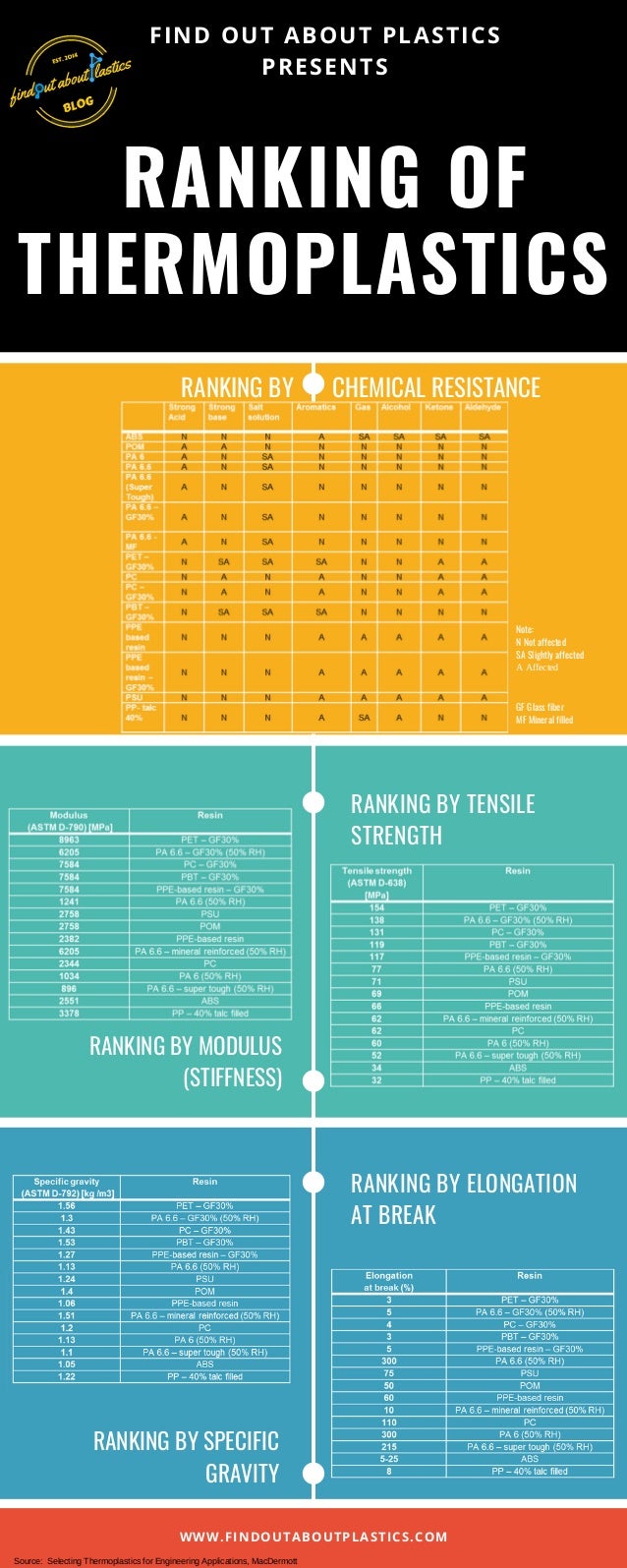
Ranking of Thermoplastics [Infographic]

Hello everyone to this post. Quick accessible knowledge about some properties of the most used engineering plastics can be key during the designing and material selection phase of your product. In this blog post I present to you an infographic which contains several tables providing design information.

Enjoy it and till next time!
Thank you for reading!

Herwig Juster
If you liked this post, share and like!
Interested in my monthly blog posts – then subscribe here.
New to my Find Out About Plastics Blog – check out the start here section.
Check out also my personal webpage.


Property Ranking of Thermoplastics - Updated Version (September 2021) 

Saturday, 18 May 2019

What is the thermal conductivity of plastics? Thermal conductivity of 96 plastics for EV application design support

Thermal conductivity of 96 plastics

In emerging electric vehicle applications which includes traction motors, battery cages, and power electronics the focus is kept more and more on the material parameter “thermal conductivity”. Removal of entrapped heat is important due to heat’s high impact on overall system performance. Thermal conductivity is the transfer of heat from one body to another body which is in contact with first. It is measured as W/mK.

The rule of thumb for thermal conductivity in plastics is as follows:
1. For amorphous thermoplastics at 0-200°C, the thermal conductivity lies between 0.125-0.2 W/mK.
2. For semi-crystalline thermoplastics at 0-200°C, values can exceed 0.2 W/mk. Inherently ordered crystalline regions lead to higher thermal conductivity

“What is the thermal conductivity of xyz-plastic?”
I created a table based on published literature, which can support you in quickly accessing thermal conductivity data of different polymers. There are some compounders which have specialized in offering thermal conductive, electrical insulated polymers, reaching over 1 W/mK.


Thermal conductivity of plastics overview
Thank you for reading and till next time!
Herwig Juster

If you liked this post, share and like!

Interested in my monthly blog posts – then subscribe here.
New to my Find Out About Plastics Blog – check out the start here section
Check out also my personal webpage.


Literature:
[1] https://omnexus.specialchem.com/polymer-properties/
[2] Saechtling Plastics Handbook

Sunday, 10 March 2019

Plastics Part Design: The Continuous Use Temperature of 124 Most Used Plastics


Hello and welcome to this blog post on the topic of continuous use temperature (CUT) of thermoplastics.

The maximum acceptable temperature for thermoplastics is one of the most critical requirements to be handled during your material selection. Above the maximum use temperature, mechanical properties (mainly tensile strength and impact strength) or electrical properties (dielectric strength) will drop significantly. On the other hand, long term retention of mechanical and other required properties over the product lifetime is crucial. Therefore, you need to be able to estimate your continuous use temperature.
Don’t worry; there are already methods out there which can assist you. There is the UL 746 which is used to calculate the Relative Temperature Index (RTI; measured in °C).

What is RTI?
Citation UL: “RTI is the temperature in °C, at which properties have decreased to 50% of their initial value after a long-term exposure to this temperature (100,000 hours)”.


The Table 1 below shows the maximum use temperature of 124 most used plastics and can assist you in your daily material selection.And below you can try out my newly developed app called "PolyTherm Selector" which allows you to select a plastic and as an output you get the Continuous Use Temperature (CUT) according UL 746B.


Table 1: Continuous Use / Service Temperature of 124 most used Plastics.

Polymer Name
Max Value (°C)
 according
UL 746 (RTI)
ABS - Acrylonitrile Butadiene Styrene
89.0
ABS Flame Retardant
95.0
ABS High Heat
110.0
ABS High Impact
100.0
ABS/PC Blend –
Acrylonitrile Butadiene Styrene/Polycarbonate Blend
110.0
ABS/PC Blend 20% Glass Fiber
110.0
ABS/PC Flame Retardant
110.0
ASA - Acrylonitrile Styrene Acrylate
90.0
ASA/PC Blend –
Acrylonitrile Styrene Acrylate/Polycarbonate Blend
110.0
ASA/PC Flame Retardant
110.0
ASA/PVC Blend –
Acrylonitrile Styrene Acrylate/Polyvinyl Chloride Blend
90.0
CA - Cellulose Acetate
95.0
CAB - Cellulose Acetate Butyrate
105.0
CP - Cellulose Proprionate
105.0
CPVC - Chlorinated Polyvinyl Chloride
100.0
ECTFE - Ethylene Chlorotrifluoroethylene
150.0
ETFE - Ethylene Tetrafluoroethylene
155.0
EVA - Ethylene Vinyl Acetate
70.0
EVOH - Ethylene Vinyl Alcohol
100.0
FEP - Fluorinated Ethylene Propylene
205.0
HDPE - High Density Polyethylene
120.0
HIPS - High Impact Polystyrene
80.0
HIPS Flame Retardant V0
80.0
Ionomer (Ethylene-Methyl Acrylate Copolymer)
48.0
LCP - Liquid Crystal Polymer
240.0
LCP Carbon Fiber-reinforced
240.0
LCP Glass Fiber-reinforced
240.0
LCP Mineral-filled
240.0
LDPE - Low Density Polyethylene
100.0
LLDPE - Linear Low Density Polyethylene
110.0
MABS - Transparent Acrylonitrile Butadiene Styrene
80.0
PA 46 - Polyamide 46
150.0
PA 46, 30% Glass Fiber
160.0
PA 6 - Polyamide 6
120.0
PA 6-10 - Polyamide 6-10
150.0
PA 66 - Polyamide 6-6
140.0
PA 66, 30% Glass Fiber
150.0
PA 66, 30% Mineral filled
140.0
PA 66, Impact Modified, 15-30% Glass Fiber
140.0
PA 66, Impact Modified
130.0
Polyamide semi-aromatic
135.0
PAI - Polyamide-Imide
280.0
PAI, 30% Glass Fiber
220.0
PAI, Low Friction
220.0
PAR - Polyarylate
130.0
PBT - Polybutylene Terephthalate
140.0
PBT, 30% Glass Fiber
140.0
PC (Polycarbonate) 20-40% Glass Fiber
125.0
PC (Polycarbonate) 20-40% Glass Fiber Flame Retardant
125.0
PC - Polycarbonate, high heat
140.0
PC/PBT Blend –
Polycarbonate/Polybutylene Terephthalate Blend
121.0
PC/PBT blend, Glass Filled
193.0
PCL - Polycaprolactone
45.0
PCTFE - Polymonochlorotrifluoroethylene
175.0
PE - Polyethylene 30% Glass Fiber
130.0
PEEK - Polyetheretherketone
260.0
PEEK 30% Carbon Fiber-reinforced
240.0
PEEK 30% Glass Fiber-reinforced
240.0
PEI - Polyetherimide
170.0
PEI, 30% Glass Fiber-reinforced
170.0
PEI, Mineral Filled
170.0
PESU - Polyethersulfone
180.0
PESU 10-30% glass fiber
180.0
PET - Polyethylene Terephtalate
140.0
PET, 30% Glass Fiber-reinforced
140.0
PET, 30/35% Glass Fiber-reinforced, Impact Modified
140.0
PETG - Polyethylene Terephtalate Glycol
63.0
PFA - Perfluoroalkoxy
260.0
PHB-V(5% valerate)
95.0
PI - Polyimide
360.0
PMMA - Polymethylmethacrylate/Acrylic
90.0
PMMA (Acrylic) High Heat
150.0
PMMA (Acrylic) Impact Modified
90.0
PMP - Polymethylpentene
110.0
PMP 30% Glass Fiber-reinforced
110.0
PMP Mineral Filled
110.0
POM - Polyoxymethylene (Acetal)
105.0
POM (Acetal) Impact Modified
100.0
POM (Acetal) Low Friction
105.0
POM (Acetal) Mineral Filled
105.0
PP - Polypropylene 10-20% Glass Fiber
130.0
PP, 10-40% Mineral Filled
130.0
PP, 10-40% Talc Filled
130.0
PP, 30-40% Glass Fiber-reinforced
130.0
PP (Polypropylene) Copolymer
130.0
PP (Polypropylene) Homopolymer
130.0
PP, Impact Modified
115.0
PPA - Polyphthalamide
140.0
PPA, 30% Mineral-filled
156.0
PPA, 33% Glass Fiber-reinforced
186.0
PPA, 45% Glass Fiber-reinforced
186.0
PPE - Polyphenylene Ether
110.0
PPE, 30% Glass Fiber-reinforced
110.0
PPE, Flame Retardant
110.0
PPE, Impact Modified
110.0
PPE, Mineral Filled
110.0
PPS - Polyphenylene Sulfide
220.0
PPS, 20-30% Glass Fiber-reinforced
220.0
PPS, 40% Glass Fiber-reinforced
220.0
PPS, Conductive
220.0
PPS, Glass fiber & Mineral-filled
220.0
PPSU - Polyphenylene Sulfone
210.0
PS (Polystyrene) 30% glass fiber
122.0
PS (Polystyrene) Crystal
80.0
PS, High Heat
90.0
PSU - Polysulfone
180.0
PSU, 30% Glass finer-reinforced
180.0
PSU Mineral Filled
150.0
PTFE - Polytetrafluoroethylene
290.0
PTFE, 25% Glass Fiber-reinforced
260.0
PVC (Polyvinyl Chloride), 20% Glass Fiber-reinforced
80.0
PVC, Plasticized
80.0
PVC, Plasticized Filled
80.0
PVC Rigid
80.0
PVDC - Polyvinylidene Chloride
90.0
PVDF - Polyvinylidene Fluoride
150.0
SAN - Styrene Acrylonitrile
95.0
SAN, 20% Glass Fiber-reinforced
95.0
SMA - Styrene Maleic Anhydride
100.0
SMA, 20% Glass Fiber-reinforced
100.0
SMA, Flame Retardant V0
100.0
SMMA - Styrene Methyl Methacrylate
100.0
UHMWPE - Ultra High Molecular Weight Polyethylene
130.0
XLPE - Crosslinked Polyethylene
82.0


Thanks for reading and #findoutaboutplastics

Greetings

Literature:

1. https://omnexus.specialchem.com/
2. Saechtling Kunststoff Taschenbuch by Erwin Baur
3. UL 746B