Tuesday 22 November 2022

Injection Molding of Plastics with Flame Retardant - 10 Important Things to Consider

Hello and welcome to a new blog post. Today we discuss the injection molding of polymers with flame retardant (FR). In general, flame retardants are added to lower the flammability of the used polymer. There are three main classes of flame retardants: nitrogen-phosphorus systems, halogenated systems, and metal-hydroxide systems. They have different working mechanisms (chemical reactions; building up a protective layer; release water for cooling) and Table 1 summarizes the advantages and disadvantages of the different flame retardant systems. 

Table 1:  Comparison of the advantages and disadvantages of the different flame retardant systems

Furthermore, the standard ISO 1043-4 shows detailed classifications of different flame retardants.

High performance polymers which have a higher level of aromatic elements in their backbone need few or no additional flame retardant at all. They  reach inherently a UL94 V-0 flammability rating with the exceptions are PSU and semi-aromatic Nylons such as PPA and PARA which need additional flame retardants to reach V-0. 

Selecting the optimal flame retardant plastic grade during material selection is one thing, processing them by injection molding is another thing, especially when you use hot runner systems. 

It is important to keep the melt processing temperature below the decomposition temperature of the flame retardant. FR-based systems are lower processed than the base polymer used. Following the processing recommendations of the material supplier is important. Also to not increase unnecessarily the melt temperature through too much shearing. 

10 Important things to Consider for injection molding of FR-plastics

1. Usage of corrosion protected plasticizing unit, hot-runner and tool: some flame retardants are corrosive since they generate acids while reacting with water. Therefore, Polyamides should have a residual moisture of below 0.2%.

2. Limitations in residence time and melt temperature: FR-plastics have a 30-40% lower residence time compared to non-FR plastics. For example, a Polyamide with 25 weight-% glass fiber (Zytel 70G25) hs a residence time of 15 minutes, where else the FR-Polyamide with 25 weight-% glass fiber (Zytel FR 70G25 V0) has a residence time of 10 minutes. Furthermore, the preferred melt temperature shall be around 15°C lower compared to the corresponding non-FR reinforced grade. 

3. Design of tool and hot-runner: usage of naturally balanced hot-runner channels (flow length from injection nozzle to injection point)

4. Design of tool and hot-runner:  usage of thermal separation is important (hot-runner with melt temperature level and tool is cooled). 

5. Design of tool and hot-runner: heating should be casted in and not only be inlaid.  This ensures a better heat transfer. 

6. Design of tool and hot-runner: enable a uniform temperature system of the hot runner by symmetric heating

7. Design of tool and hot-runner: prevent dead corners in the hot runner by using separator inserts (redirection of melt). 

8. Design of tool and hot-runner: make the hot runner nozzles interchangeable in case wear is damaging the nozzles. 

9. Design of tool and hot-runner: consider good thermal separation in the nozzle area. Otherwise local high temperatures lead to a reaction of the flame retardant. 

10. Design of tool and hot-runner: usage of temperature sensors with PID capability (photoionization detector) to optimally control temperatures of each runner nozzle. 

Conclusions

When using a FR-plastic grade, keep your processing temperature as low as possible. Prevent too much shearing over the complete processing length (plasticizing unit, hot runner and tool) and reduce local overheating of the material. Also keep residence time to minimum and always keep in mind that the flame retardant can start reaction during processing. 

What are your experiences with flame retardant plastics - let me know in the comment section. 

Thanks for reading and #findoutaboutplastics

Greetings

Herwig 

Interested to talk with me about your polymer material selection, sustainability, and part design needs - here you can contact me 

Subscribe to my Polymer Material Selection book launch page 

Interested in my monthly blog posts – then subscribe here and receive my high performance polymers knowledge matrix.

Literature: 

[1] DuPont - Serie Kunststoffpraxis Teil 8: Kunststoffe mit Flammschutz, 2003

[2] Erwin Baur, Dietmar Drummer, Tim A. Osswald, Natalie Rudolph: Saechtling Kunststoff-Handbuch, Hanser Verlag

Tuesday 15 November 2022

Design Properties for Engineers: Chemical Resistance of Plastics - An Overview for Material Selection

Hello and welcome to a new post in which we discuss the chemical resistance of commodity and engineering polymers. High performance polymers we discuss in this post here.

Chemical Resistance of Plastics

In general, the chemical resistance of polymers towards certain chemical compounds can be estimated at different temperatures and times. Usual tests are conducted at room temperature for 30 days [1]. In material selection, the preparation phase is a key success element. During this phase it is important to collect as much information on environmental conditions as possible (consider the trinity of thermal, chemicals and time). 

Table 1 supports you in this phase. The chemical resistance of selected commodity and engineering plastics was tested and compared to each other. It can be a first indication, however your specific grade must be checked again towards the chemical it will be exposed to in the final application. Most material suppliers have already done extensive testing to make things faster and easier for you. 

Table 1: Chemical Resistance of Plastics - An Overview for Material Selection

Additionally, I created an interactive dashboard using Tableau which allows you to fast filter the polymer and the chemical for a fast analysis: 


Also, I made a short training video on this topic: 

Check out the other Design Properties for Engineers posts. 

Thanks for reading and #findoutaboutplastics

Greetings

Herwig 

Interested in my monthly blog posts – then subscribe here and receive my high performance polymers knowledge matrix.

!NEW! Ultra and High Performance Polymer Selection - new online course coming soon - join the waiting list

Literature:

[1] https://www.buerkle.de/files_pdf/wissenswertes/technology_properties_of_plastics_en.pdf

[2] Erwin Baur, Dietmar Drummer, Tim A. Osswald, Natalie Rudolph: Saechtling Kunststoff-Handbuch, Hanser Verlag 


Wednesday 9 November 2022

Plastic Multipoint Design Data: Creep Strain of Amorphous and Semi-Crystalline Polymers

Hello and welcome to a new blog post. Today I present to you another important multipoint and long-term data set for polymer material selection and part design: tensile creep modulus. 

The creep strength and toughness of High Performance Plastics we discuss here

Mechanism of creep

Creep, also known as cold flow, is the deformation under a static load over time and helps to gain insights over the product lifetime. Understanding the creep behavior is one puzzle key during polymer material selection. Creep resistance materials are needed for applications such as structural components, joints, fittings and hydrostatic pressure vessels.  In general we can distinguish between primary, secondary, and tertiary creep.  When you conduct a creep test it is important to keep the applied stress on the material at a constant level. This allows in turn to plot  the lifespan of your product.

Primary, Secondary, and Tertiary Creep

Exposure to heat or load will result in a strain reaction of the polymer. It is the stretching and straining of the entanglements with the macro molecular network. The polymer passes relatively rapid through this first phase. 

The primary creep rate decreases and we see a steady state phase of the creep. This is also known as strain hardening. Polymers undergo a linear progression during this second phase. The secondary creep phase is much longer than the first and is relevant for estimation of the part failure time. 

The last phase is again a rapid phase. Microstructural changes such as internal cracks will lead to a fast failure of the part. 

Creep behavior of amorphous  and semi-crystalline polymers

Main creep mechanism of amorphous polymers is molecular de-tangling, slipping, and rearrangement. On the other hand, the creep of semi-crystalline polymers is restricted by the crystalline regions. 

Table 1 shows the creep behavior of amorphous and semi-crystalline polymers at a stress level of 8 to 9 MPa at 31°C.

Table 1: Creep behavior of amorphous and semi-crystalline polymers at a stress level of 8 to 9 MPa at 31°C.

More multipoint design data you can find here

Thanks for reading and #findoutaboutplastics

Greetings, 

Herwig 

Interested to talk with me about your polymer material selection, sustainability, and part design needs - here you can contact me 

Subscribe to my Polymer Material Selection book launch page 

Interested in my monthly blog posts – then subscribe here and receive my high performance polymers knowledge matrix.

Literature:

[1] DuPont -  Design Guide

[2] https://www.xcentricmold.com/the-impact-of-creep-in-plastics/

[3] https://www.researchgate.net/publication/317206602_Long-term_Loading_-_Tensile_Creep_Modulus_-_data/download

Wednesday 2 November 2022

Polymer Material Selection: How Can the Flow and Chemical Resistance of Amorphous Polymers be Improved?

Hello and welcome back to a new blog post. Today we discuss a question that I received in the context of polymer material selection: How can the flow and chemical resistance of amorphous polymers be improved?

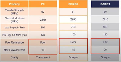
One effective way to improve the flow of amorphous polymers is by alloying them with semi-crystalline polymers. In Table 1 the example of Polycarbonate is shown which is alloyed with ABS and PBT. 

Table 1: Blending PC with ABS and PBT to improve flow and chemical resistance

PC itself has good all over mechanical values and excellent impact behavior. However, fuel resistance is poor and also injection moulding is more challenging. Alloying a PC with ABS results in a material which has better flow properties. Fuel resistance remains at the same bad level. Alloying PC with PBT we can improve both: lifting fuel resistance to a fair level and double the melt flow. You have the toughness of a PC combined with the solvent resistance of PBT. Your product will have good heat, chemical, and impact resistance with good mouldability. 

Why are polymer blends useful during the material selection process?

Polymer blends help to fulfill open product requirements since most polymers show a lack of certain properties (flexibility, transparency, low density). Also, lower material costs can be achieved with polymer blends. 

Thanks for reading and #findoutaboutplastics

Greetings, 

Herwig 

Interested to talk with me about your polymer material selection, sustainability, and part design needs - here you can contact me 

Subscribe to my Polymer Material Selection book launch page 

Interested in my monthly blog posts – then subscribe here and receive my high performance polymers knowledge matrix.

Literature: 

[1] https://www.youtube.com/watch?v=nLGcSszTaTs

[2] https://www.youtube.com/watch?v=QrbHcEagUZM